 SEAL CONNECT
API Flush Plans for Mechanical Seals
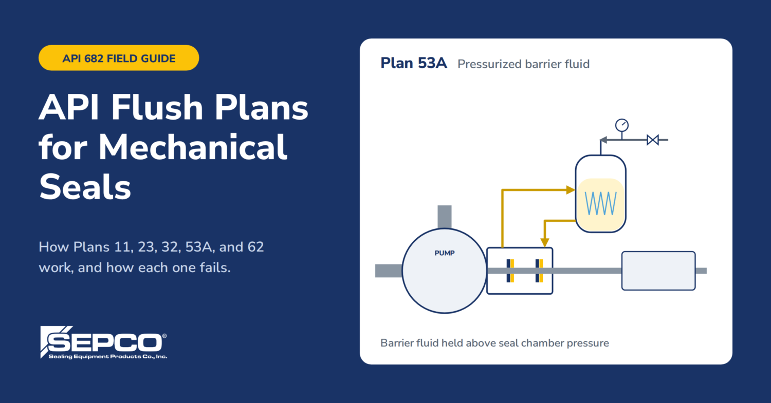 API flush plans are the standard seal piping arrangements defined in API 682. Each numbered plan specifies how fluid is supplied to, cooled, filtered, pressurized, or drained from a mechanical seal so the faces run in a stable environment.
A mechanical seal lives or dies on what’s in the seal chamber. The faces run on a fluid film a few microns thick, and that film has to stay liquid, clean, and cool enough to carry load. Pump the product as-is past the faces and you get flashing at the faces, solids packing the springs, crystallization on the atmospheric side, or heat checking on the hard face.
Each plan number describes a piping arrangement: where the flush comes from, whether it’s cooled, filtered, or throttled, and what happens on the atmospheric side. Learn the dozen that cover most plants and you can read a seal drawing at a glance.
The plan has to match the fluid, the pump, and the operating point. A plan that works on a 40 °F water service will cook a seal on 450 °F hot oil. When in doubt, check the seal manufacturer’s IOM and the pump datasheet before changing piping.
Single-seal flush plans: 11, 13, 14, 21, 23, 32
These plans put fluid into the seal chamber on the process side of a single seal. Plan 11 is the default on most clean services; the rest exist because Plan 11 doesn’t work everywhere.
| Plan | Arrangement | Use it on | What goes wrong |
|---|---|---|---|
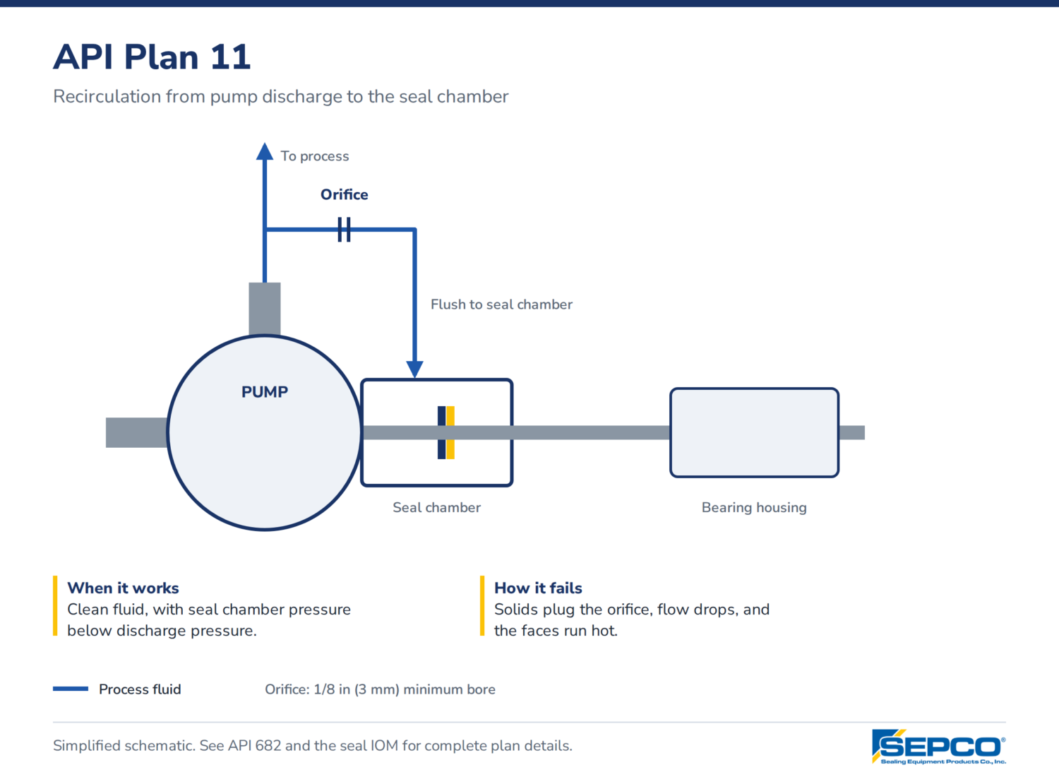
| 11 | Recirculation from pump discharge through an orifice to the seal chamber | Clean fluids, chamber pressure below discharge | Orifice plugs with solids; flow drops and the faces run hot |
| 13 | Recirculation from the seal chamber back to pump suction | Vertical pumps (vents the chamber); chamber pressure near discharge | Low flow if suction and chamber pressures are close; doesn’t cool a hot product |
| 14 | Plan 11 and Plan 13 combined | Vertical pumps that need both venting and flush flow | Two orifices to size and two lines to plug |
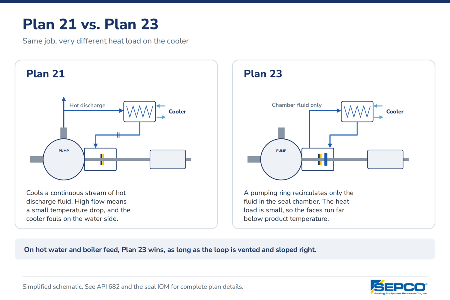
| 21 | Plan 11 through a cooler | Hot water and hydrocarbons where the product near the faces would flash | Cooler fouls on the water side; flow is high, so the cooler works hard for little temperature drop |
| 23 | Closed loop: pumping ring circulates chamber fluid through a cooler and back | Boiler feed water and hot water above roughly 180 °F | Pumping ring won’t move fluid if the loop isn’t vented or slopes wrong; it’s the best-performing hot-water plan when piped right |
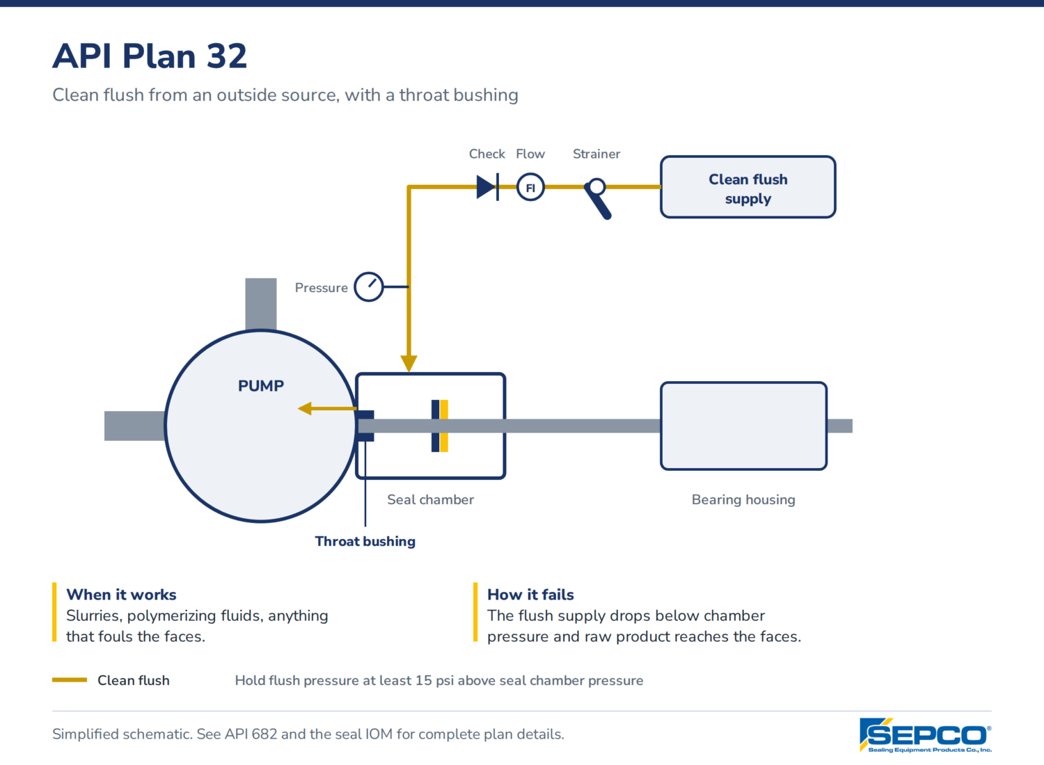
| 32 | Clean flush from an outside source, with a throat bushing | Slurries, polymerizing fluids, or anything that fouls the faces | Product dilution; flush lost to supply upset leaves the faces in raw product |
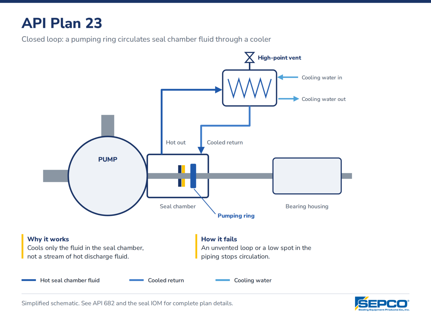 Plan 23 deserves the extra attention. It cools only the small volume in the chamber, not a stream of hot discharge fluid, so the same cooler holds the faces far below product temperature. That only works if the loop vents at its high point and the piping runs uphill to the cooler with no low spots.
Plan 32 trades seal life for product dilution and flush cost. On a slurry pump that’s usually the right trade. Size the flush for 3 to 5 ft/s through the throat bushing clearance so solids can’t migrate back, and confirm the supply pressure holds at least 15 psi above chamber pressure across the operating range.
Dual-seal plans: 52, 53A, 53B, 53C, 54
Dual seals use a second fluid between the inboard and outboard seals. Unpressurized buffer fluid (Plan 52) backs up a leaking inboard seal. Pressurized barrier fluid (Plans 53 and 54) keeps the process off the inboard faces entirely, so a seal leak puts barrier fluid into the product instead of product into the atmosphere.
| Plan | Arrangement | Use it on | What goes wrong |
|---|---|---|---|
| 52 | Unpressurized buffer reservoir, vented to flare or recovery | Light hydrocarbons and volatile services where some inboard leakage is acceptable | Nobody watches the level; a rising level means the inboard seal is leaking and gets ignored until the outboard fails |
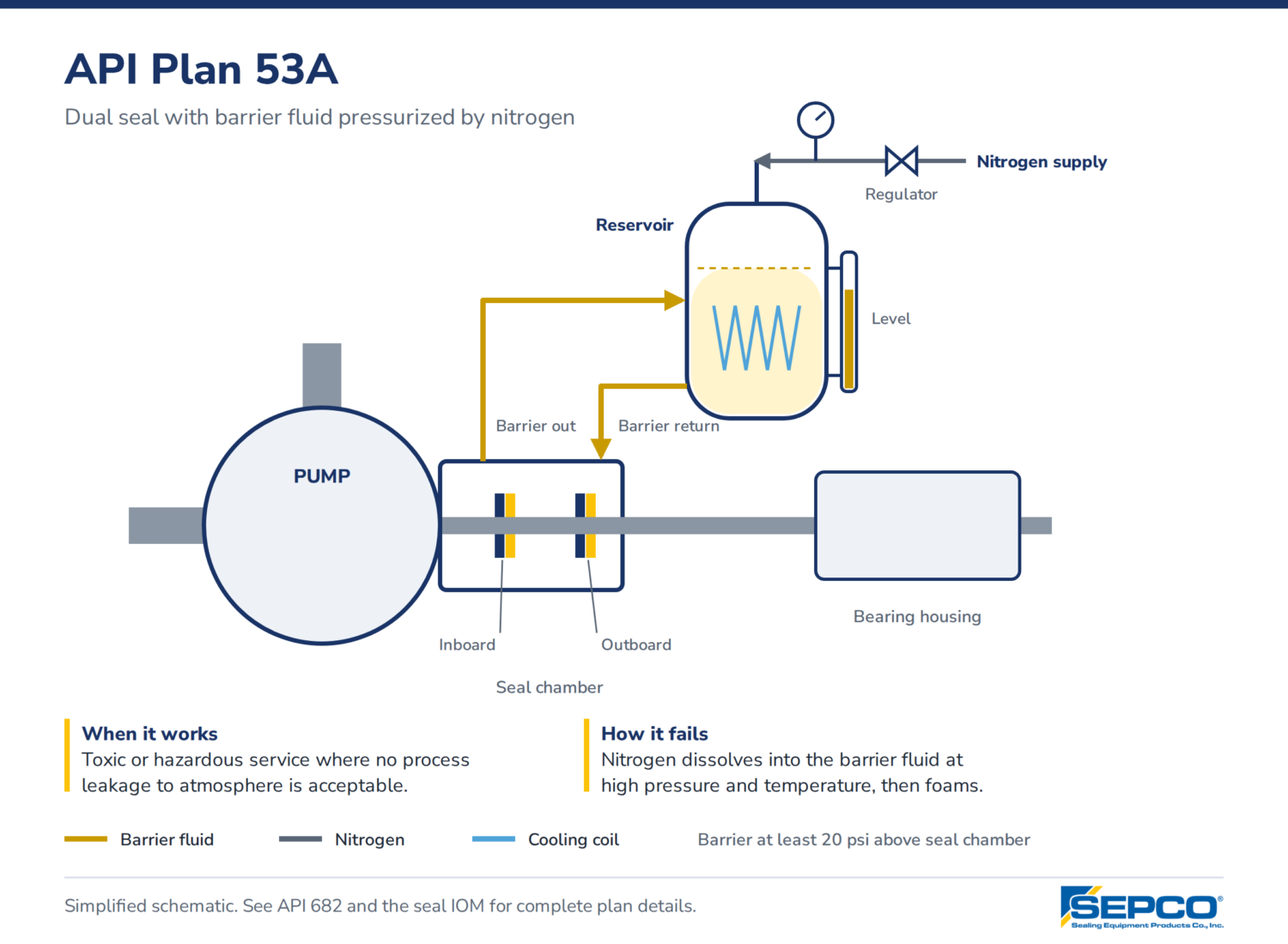
| 53A | Barrier reservoir pressurized by nitrogen | Toxic or hazardous services up to about 150 psi barrier | Nitrogen dissolves into the barrier fluid at higher pressure and temperature, then foams at the faces |
| 53B | Barrier circuit pressurized by a bladder accumulator | Higher pressure, where gas absorption rules out 53A | Bladder precharge drifts; operators refill without recalculating the pressure-volume curve |
| 53C | Barrier pressurized by a piston accumulator referenced to seal chamber pressure | Services with swinging chamber pressure | Piston sticks or the reference line plugs, and barrier pressure stops tracking |
| 54 | Barrier fluid supplied by an external pressurized system | Multiple seals on one console, or high heat loads | One supply failure takes every seal on the system with it |
Set barrier pressure at least 20 psi above the highest seal chamber pressure the pump will see, including startup and upset. Check the seal drawing; some designs call for more.
When piping a reservoir, API 682 sets these minimums. Confirm them against the edition your site works to:
- Tubing: 1/2 in for shafts up to 2.375 in (60 mm); 3/4 in above that. Austenitic stainless is the standard.
- Slope: lines rise continuously from the gland to the reservoir at about 1/2 in per foot. A single low spot traps vapor and stops thermosyphon flow.
- Reservoir volume: at least 3 gal for shafts up to 2.375 in; 5 gal above.
- Reservoir construction: the vessel is built to pressure vessel code (ASME Section VIII in the U.S.); the connecting piping follows ASME B31.3.
- One reservoir per seal. Sharing a reservoir between pumps hides which seal is leaking.
Quench and leakage plans: 62, 65, 75, 76
These plans work on the outboard side of the seal. They don’t cool the faces; they deal with what leaks past them.
| Plan | Arrangement | Use it on | What goes wrong |
|---|---|---|---|
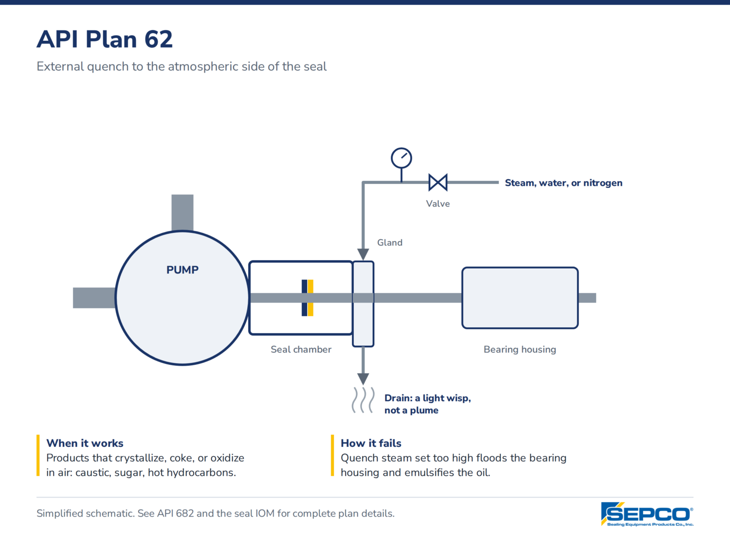
| 62 | External quench (steam, water, or nitrogen) to the atmospheric side | Products that crystallize, coke, or oxidize on contact with air: caustic, sugar, hot hydrocarbons | Steam quench run too hot or too wet floods the bearing housing and emulsifies the oil |
| 65A/B | Leakage drain to a collection point with a level or flow alarm | Single seals where you need to know about a failure before it’s on the floor | Alarm gets bypassed after the first nuisance trip |
| 75 | Containment seal drain to a collection vessel | Condensing leakage from dual containment arrangements | Drain line plugs; the vessel never fills, so the failure goes unseen |
| 76 | Containment seal vent to flare or vapor recovery | Non-condensing leakage | Back pressure from the flare header pushes vapor back into the containment cavity |
The steam quench in Plan 62 is where most bearing damage gets blamed on the seal. Keep quench steam at 2 to 3 psig, enough to show a light wisp at the drain. A plume means it’s too high, and that moisture ends up in the oil sump. A bearing isolator on the pump side of the bearing housing is cheap protection on any quenched pump.
Why seal flush plans fail in the field
Most flush-plan failures are piping and maintenance problems, not seal problems. The seal gets pulled, the faces show heat checking or blistering, and the replacement fails the same way because the piping never changed.
- Orifice too small or plugged. API 682 sets a 1/8 in minimum bore. If you need more restriction than that, use multiple orifices in series, spaced apart, not one smaller one.
- No way to read pressure. On Plan 32 and any external flush, install a gauge with block valves on both the flush line and the seal chamber. Without them, nobody can confirm the flush is above chamber pressure.
- Cooler piped backward. Process fluid goes through the tubes and cooling water on the shell side. Reverse it and the shell side scales up in a season. Specify a removable head, bolted or studded, so the tubes can be cleaned.
- Valves left closed after maintenance. A Plan 11 or 21 with an isolation valve closed runs the seal dead-headed. Lock valves open or remove the handles.
- Low spots and long runs. Any loop that relies on thermosyphon or a pumping ring (23, 52, 53) fails if the line dips or snakes. Keep runs short and sloped uphill.
How to choose an API flush plan
Start with the fluid and the margin between seal chamber pressure and vapor pressure at chamber temperature. If the margin is under 25 psi, or the product runs above about 180 °F, Plan 11 alone is likely to flash at the faces. Move to 21 or 23. If the product carries solids or polymerizes, go to 32. If leakage to atmosphere isn’t acceptable, go to a dual seal with 52 or 53.
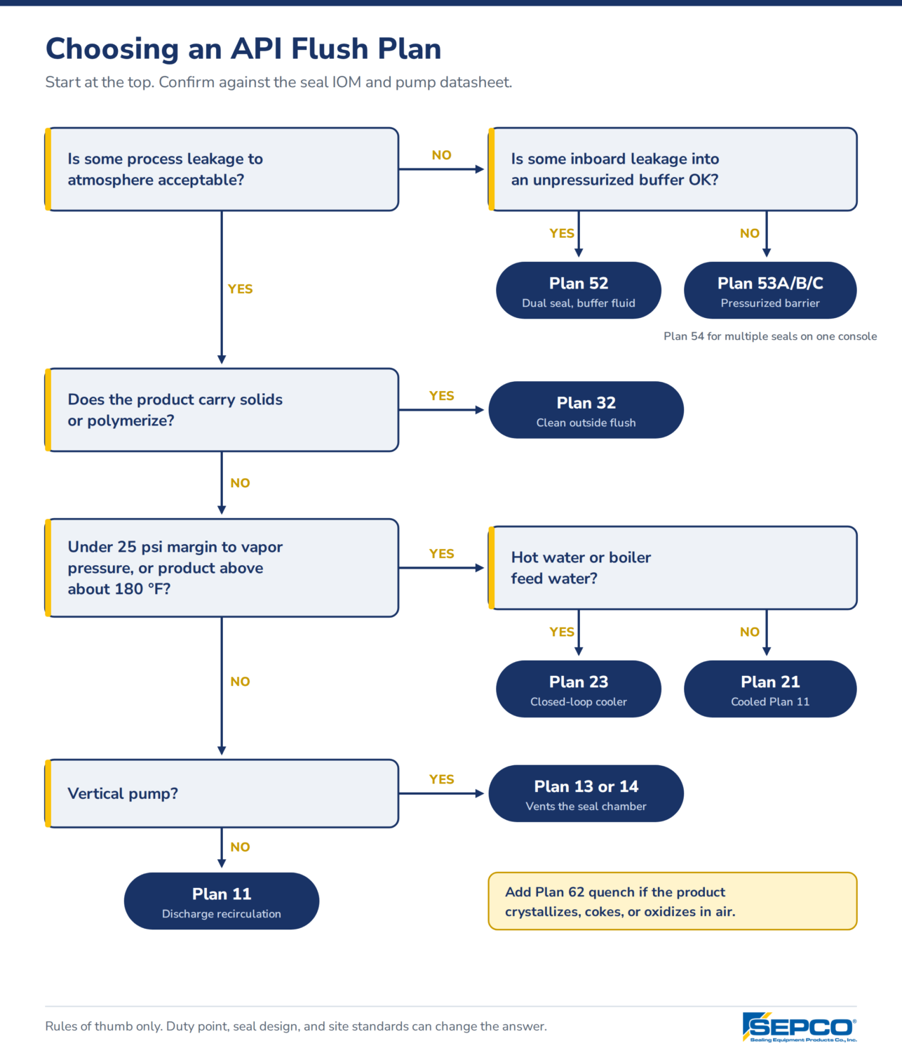
It depends on the pump, the duty point, and the seal design, so check the seal IOM and the pump datasheet before changing a plan. SEPCO’s installation drawings for our cartridge, DTP, DGS, ESD, and RBD seals show the plan connections for each model. For more on chamber pressure, read Seal Chamber Pressure and Balance Ratio. For help picking a plan on a specific pump, call SEPCO at 205.403.7500.
Frequently asked questions
What is an API flush plan?
An API flush plan is a standard piping arrangement from API 682 that controls the fluid around a mechanical seal. The plan number tells you where the flush comes from, whether it’s cooled, filtered, or pressurized, and how leakage is handled.
What is the difference between Plan 11 and Plan 23?
Plan 11 sends pump discharge fluid through an orifice into the seal chamber. Plan 23 circulates the seal chamber fluid in a closed loop through a cooler using a pumping ring. Plan 23 is the better choice for hot water because it cools only the chamber volume.
When should you use Plan 53 instead of Plan 52?
Use Plan 53 when no process leakage to atmosphere is acceptable. Plan 53 pressurizes the barrier fluid above seal chamber pressure, so a leak puts barrier fluid into the product. Plan 52 uses unpressurized buffer fluid and tolerates some inboard leakage.
What is the difference between buffer fluid and barrier fluid?
Buffer fluid sits between two seals at a pressure below the seal chamber (Plan 52). Barrier fluid is held above seal chamber pressure (Plans 53 and 54), so it, not the product, lubricates the inboard seal faces.
What does a Plan 62 quench do?
Plan 62 feeds steam, water, or nitrogen to the atmospheric side of the seal. It keeps leakage from crystallizing, coking, or oxidizing on the faces. It does not cool the seal faces.
What is the minimum orifice size for a seal flush?
API 682 sets the minimum orifice bore at 1/8 in (3 mm). If you need more restriction, install multiple orifices in series rather than one smaller orifice.
 Find Your Sealing Solution